Where do I measure?
Patient positioning & shear-wave elastography protocol for the torn supraspinatus
Step 1 — patient positioning
1Modified Crass position
The patient sits upright with the affected arm placed behind the back, palm resting on the lower lumbar region (opposite iliac crest). This rotates the supraspinatus anteriorly out from under the acromion and brings its footprint onto the antero-superior humeral head, where it is accessible to the transducer.
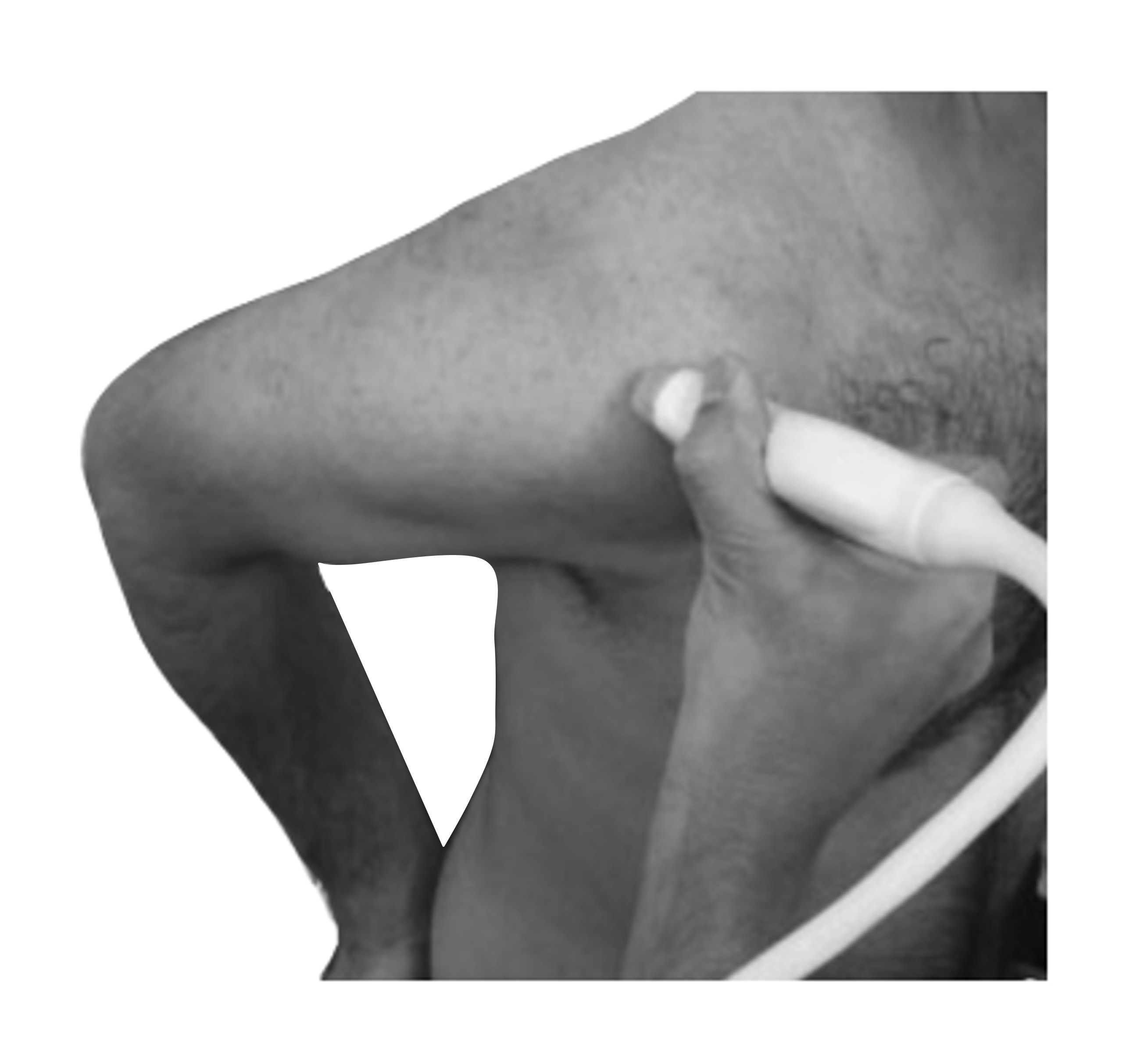
Figure 1. Modified Crass position. Probe placed over the antero-superior shoulder, long axis aligned with the supraspinatus tendon fibres. Keep probe contact firm but avoid excessive compression — tissue pre-load alters SWE velocity.
Step 2 — transducer placement & ROI
2Long-axis view, ROI over the footprint
Orient the linear probe along the long axis of the supraspinatus. Identify the tendon footprint insertion at the greater tuberosity (and the suture anchor if the tendon has been repaired). Place the shear-wave ROI box over the tendon substance just medial to the footprint, at the same level where re-tears typically occur.
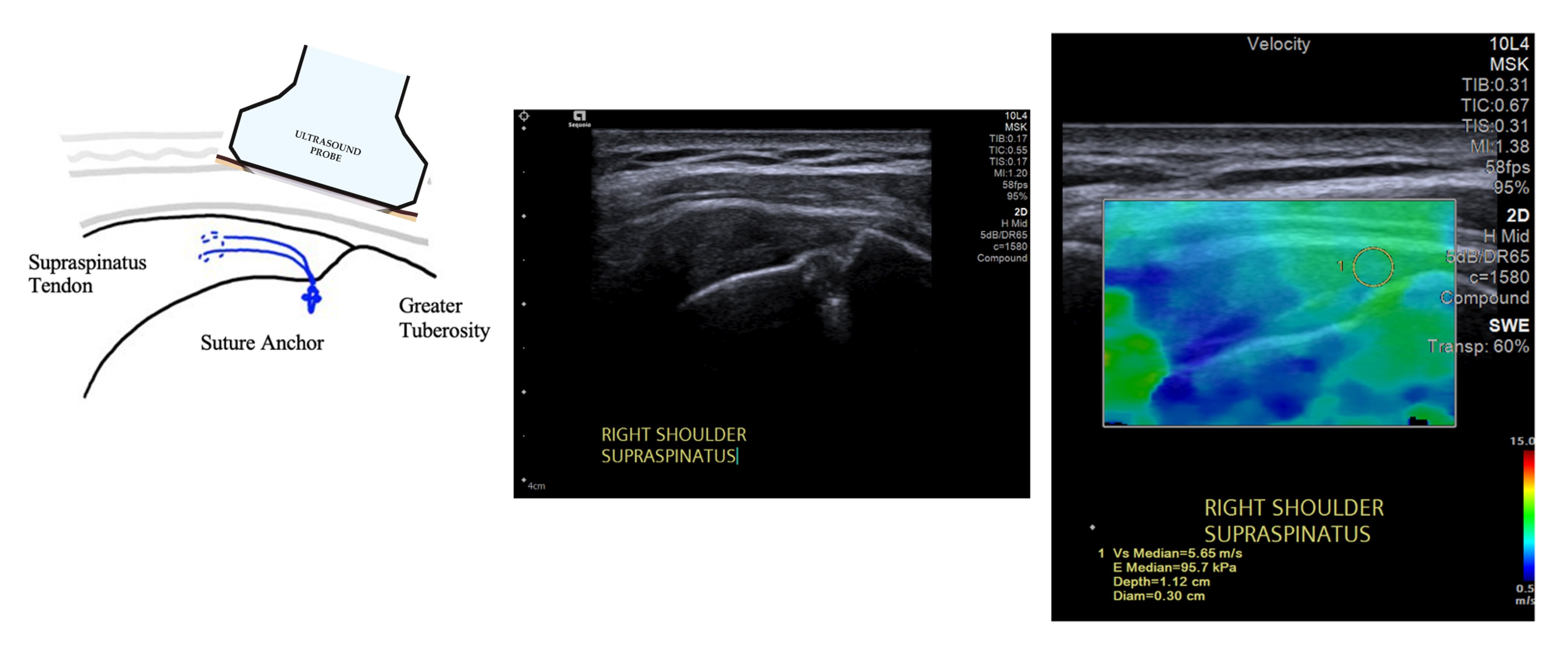
Figure 2. Left — anatomical schematic. Probe aligned along the supraspinatus long axis; suture anchor sits at the footprint on the greater tuberosity. Middle — corresponding B-mode image: supraspinatus tendon, footprint and greater tuberosity. Right — shear-wave elastography overlay; a ~3 mm circular ROI is placed within the tendon substance at the footprint level (here: Vs median = 5.65 m/s, E median = 95.7 kPa).
Key tips for reliable measurements
- Probe pressure: just enough for coupling — any visible tendon compression will artificially raise velocity.
- Long axis: keep fibres horizontal on the B-mode image; off-axis measurements are unreliable.
- ROI placement: within tendon substance at the footprint, away from the bony cortex and away from the suture anchor artefact.
- Patient relaxed: the arm hanging passively behind the back — no active abduction or external rotation.
- Repeat × 3: take three independent acquisitions and record the median Vs. Discard frames with a noisy / incomplete colour map.
- Breath-hold optional: respiration rarely affects values, but a quiet breath-hold is cleanest.
Machine settings used in the study
| Ultrasound system | Siemens Acuson Sequoia (10L4 linear transducer) |
| Mode | 2D shear-wave elastography, velocity display (m/s) |
| Depth | ~1.0 – 1.5 cm (tendon at footprint) |
| ROI | Circular, ~3 mm diameter, within tendon substance |
| Reported value | Median Vs (m/s) across 3 acquisitions |
| Dataset SWE range | 2.2 – 10.6 m/s (n = 114) |
SWE values are machine- and operator-dependent. Absolute velocities are most comparable when the same system, probe and ROI size are used. The predictive model presented on the calculator page was derived on the above protocol.